A while back I made a case for getting new lights installed throughout the house as we were re-wiring the house and replacing the electrical panel as part of some renovations.
We already had one LIFX bulb in the house and decided to buy their Colour Downlights and LED strips. We initially started with a total of 44 LIFX devices:
- 40x LIFX WiFi LED Colour 100mm Standard Downlight 13W (LH4DK1UC08AU)
- 1x LIFX Lightstrip 1 Metre (LZ3TV1MAU)
- 1x LIFX Lightstrip 2 Metre (LZ3SK2MAU)
- 1x LIFX Lightstrip 1 Metre Extension (LZ1RGBWAU)
- 1x LIFX Colour 1200 Lumens A60 B22 Bulb (LHLA19B22AU) to go with the existing bulb that we moved out to the garage.
Since then we’ve also added 6 more bulbs to lamps and have plans for 3 more LED strips in the future. We acquired these 6 LIFX bulbs:
- 1x LIFX Candle White to Warm E14 (LCDDE14IN)
- 2x 2 Pack of LIFX White 800 B22 (HB2L3A19LW08B22AU)
- 1x LIFX Mini White 9W B22 (L3A19MW08B22)
We’re very happy with the LIFX lights so far and in over a year have only had to RMA one bulb which was quite seamless. Adopting them all wasn’t the easiest process and was made frustrating when the electricians accidentally factory reset them all as they tested the new electrical panel, however overall the process was easy and worth the time investment.
Light Buttons
After some time having the lights wired with traditional light switches we got to the point where the switches were limiting what we were able to do with the lights and began looking at alternate solutions.
All of our lights are integrated directly with Home Assistant and we wanted something that would not require further re-wiring or to expand the electrical panel with relays or other controllers.
Long term we’re still considering using the OXRS platform however for now we’ve gone down a the DIY path.
A proof of concept
We already had a number of ESPHome based projects around the house and decided to use our existing collection of assorted components to figure out what direction we want to go and to try things out.
We knew a few things before going down this path:
- We didn’t want to change the electrical wiring or remove the light switches entirely
- We wanted to use momentary buttons instead of switches
- We wanted to have some kind of LED indicator for the buttons
- to indicate their status
- to help find them at night
- We wanted something simple yet effective that could be made nicer as we iterated and learnt
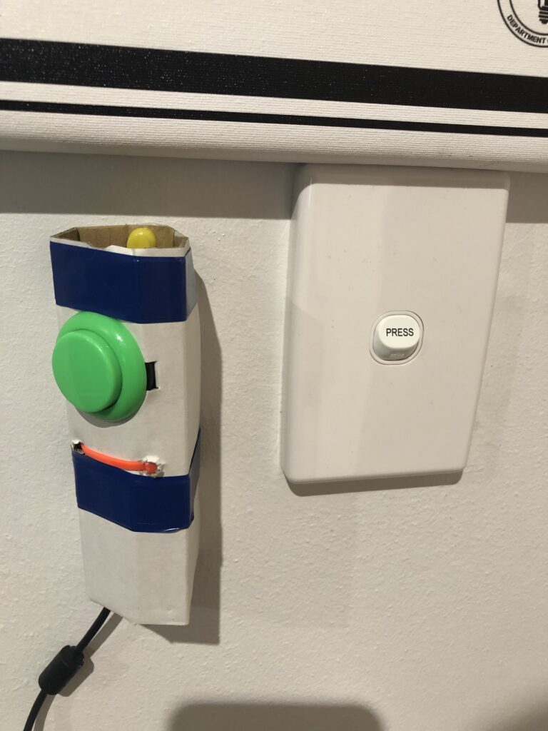
We started in our home office by hooking an arcade button up to an ESP8266, mounting it in some cardboard and pinning it to the wall near the light switch.
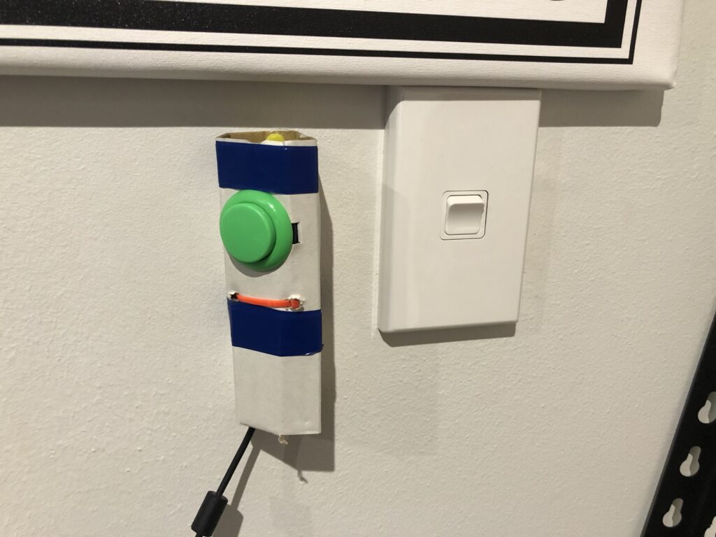
The circuit was incredibly simple with just the button, two wires and the ESP8266. This setup was incredibly reliable for a thing that was barely attached to the wall and was powered from a nearby computers USB port.
We decided to keep things consistent with our other projects by only using the Node-RED add-on to manage the entity for the button and not any direct features in Home Assistant itself.
The second iteration
We used this button for weeks and the only problems we experienced were that the ESP8266 wouldn’t function without power and that the lights themselves couldn’t function if the light switch was turned off.
For the second iteration we moved to solve only those two problems.
The easiest way to do this was to remove the external nature of the temporary button. We had the existing light switch removed from the face plate, it was taped into the on position and left in the wall. A single Ethernet cable was pulled down from the roof space to the light switch and one pair (two wires) were connected to a momentary light switch mechanism.
The ESP8266 was moved into the roof space and is now powered from a power point in the roof. The circuit was effectively the same as the proof of concept but with a longer cable and a significantly more polished appearance. The initial proof of concept was removed from the wall.
Going from the arcade button to the momentary mechanism meant there was a difference in the sound produced. While the new sound was not louder, it was more significant and could be heard throughout the house.
Expanding the trial
Having a more permanent setup in the office gave us the confidence to expand the trial to the main bedroom, our sons bedroom and to our front doorbell.
I drilled a hole in a blank face plate and installed a small momentary push button for the main bedroom, we did similar for our sons room only with an arcade button and we also installed another button for the front doorbell.
Ethernet was pulled to each location and the existing light switches in the two bedrooms were hidden in the wall just like the one in our home office.

It was becoming quite apparent that we all liked where the trial was going. The buttons were all incredibly responsive and worked much more reliably than expected, even though the ESPs are using WiFi and have stripped Ethernet barely pushed into their headers.
Trying new things
Because we had expanded from a single room that we normally only occupy during daylight hours, we were also able to explore new areas of lighting control.
Thanks to my many years of being on-call I am often unable to get back to sleep once I’ve seen any bright light at night. We were able to test using dim red lighting during our sleeping hours and this was life changing for me. Having this ability to use dim red lighting at night significantly increased my desire to replace our light switches.
Learning a few lessons
With our desire to use momentary buttons instead of switches we needed to get the state of the light away from the light switch and into Home Assistant. We had partially done this with the second iteration as the lights always had power and a button push would trigger a “toggle” of the lights between off and on.
During this time our son transitioned to a loft bed and was not enjoying getting out of bed and going down a ladder to turn off his lights, only to then climb the ladder and get back into bed in the dark. We decided to stick a ZigBee button to the wall near his pillow which also toggled the lights in his room.
This led to us discovering two problems:
- He liked to repeatedly push his buttons to strobe his lights
- He could now easily turn his lights on when he was supposed to be asleep
Problem one was pretty simple to solve, we talked about why we didn’t want him to strobe his lights and added a rate limit into the Node-RED flow for his buttons which limited them to one push every five seconds.
Problem two was more interesting as he also had a habit of waking up very early in the morning to play only to be too tired for a full day at school. We talked with him and decided to try out dim red lighting in his room at night.
We set Node-RED to make his lights dim red between his bedtime and a sane wake up time so that there is enough light to make it to and from bed and the door but not enough to play or sit up and read. Thankfully this change has been quite effective and has led to him both getting more sleep and behaving better at school.
Better buttons and Face Plates
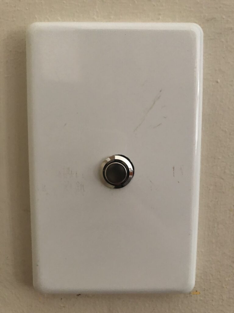
Unfortunately the buttons we had were all audibly annoying and inconsistent so I started to look at alternative options. I ended up deciding to go for a well priced option from AliExpress which had a “high head” (a bit that sticks out and makes them easier to push) and a yellow LED ring.

I had a few blank face plates that I was planning to drill into in order to mount the buttons. Unfortunately I hadn’t yet managed a nicely centered hole without also scratching the face plate. The slightly different look of the blank face plates was also significantly different in feel to a normal light switch.
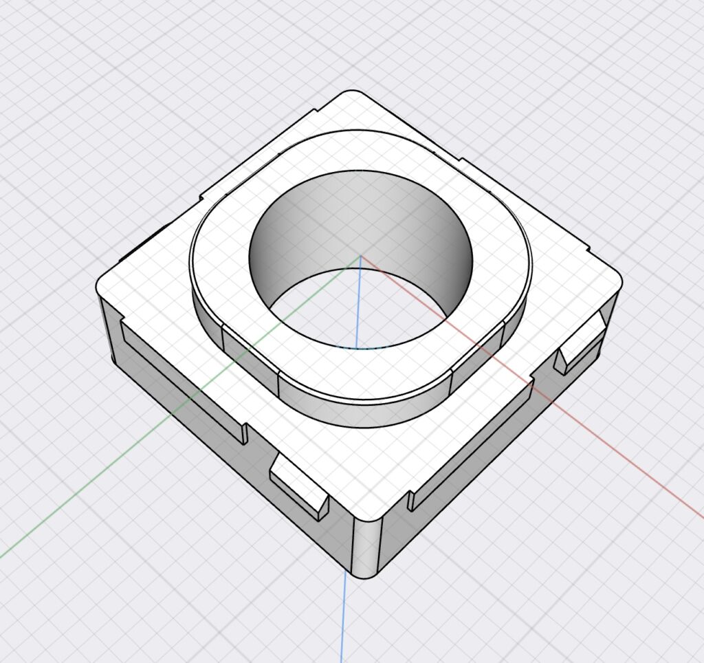
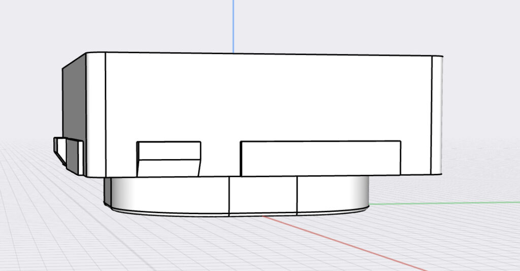
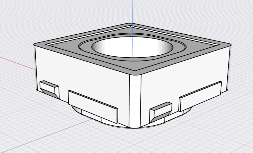
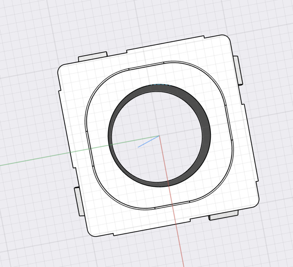
The Design
While looking at the options for mounting the buttons I realised we had a number of Amdex plates from our Ethernet cabling. I briefly considered drilling holes in their ‘blanking inserts’ before discovering this blank insert design by Rushil Kilsoon.
I modified Rushil’s design to add a 13mm hole which nicely fits the 12mm buttons. The modified version of the design is on Thingiverse here.
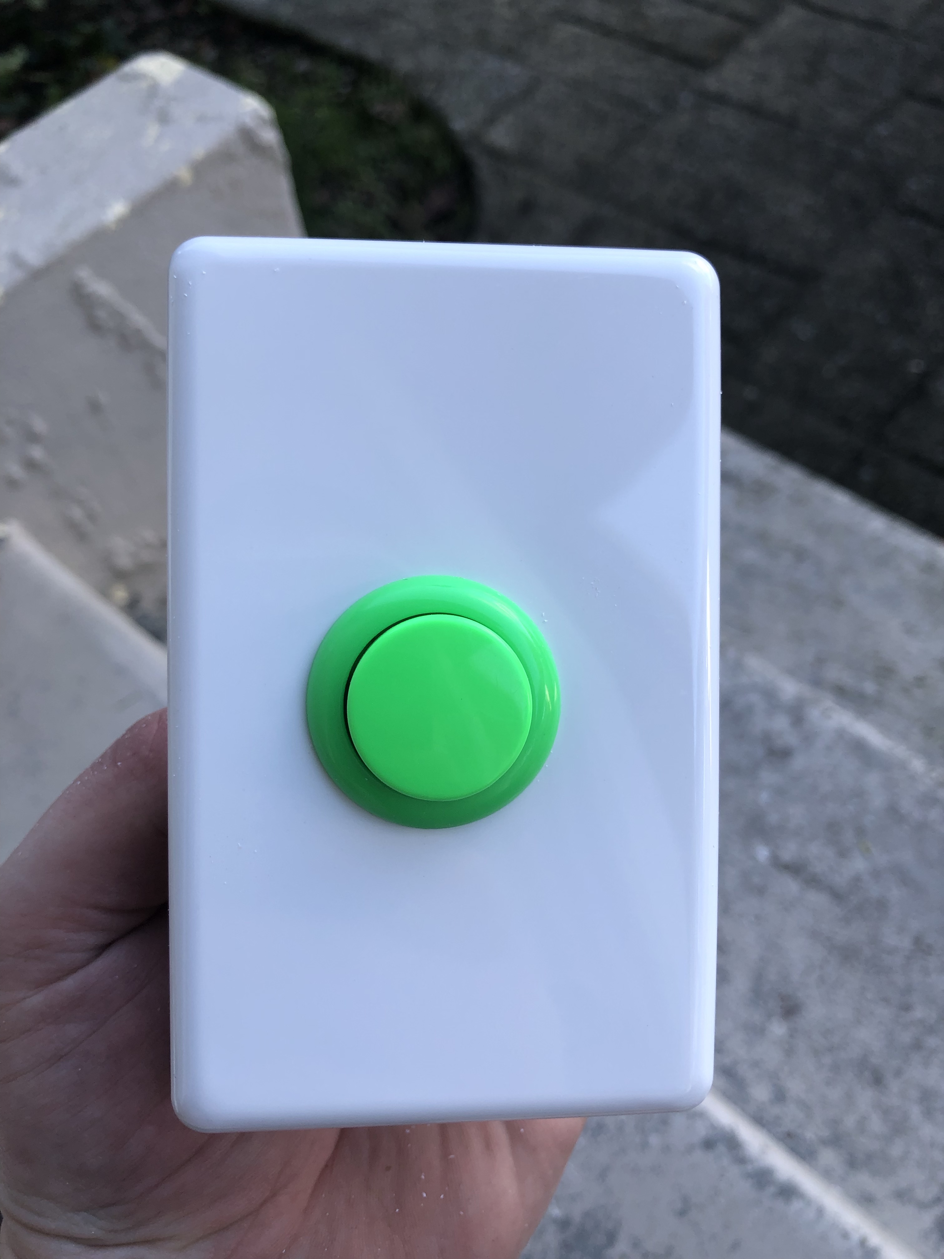
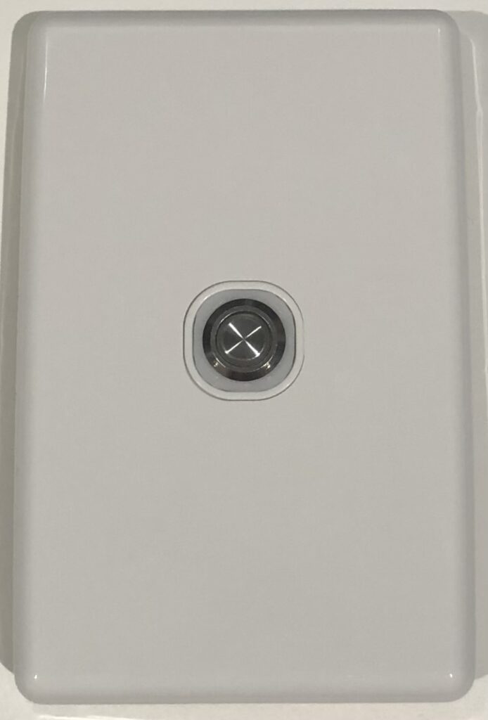
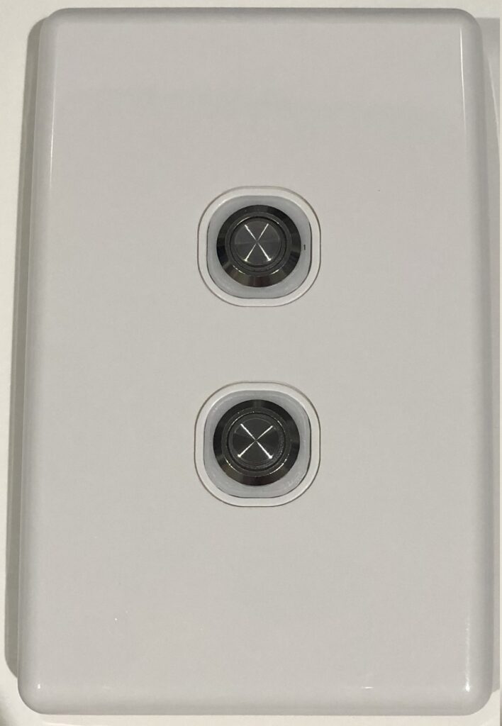
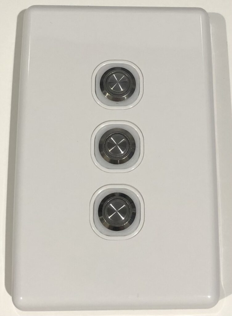
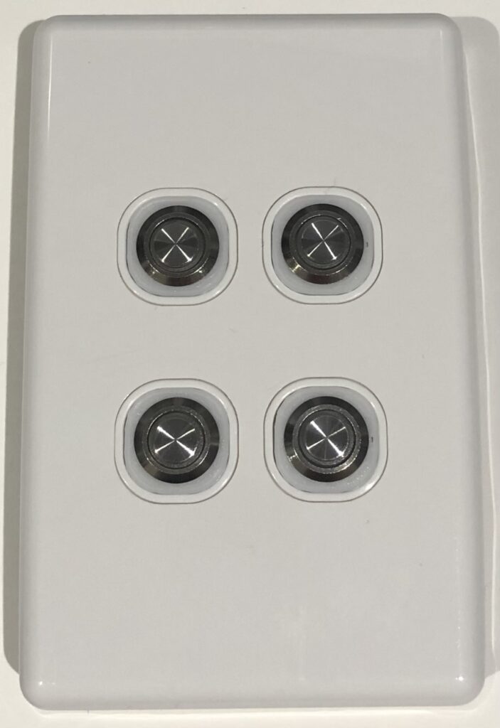
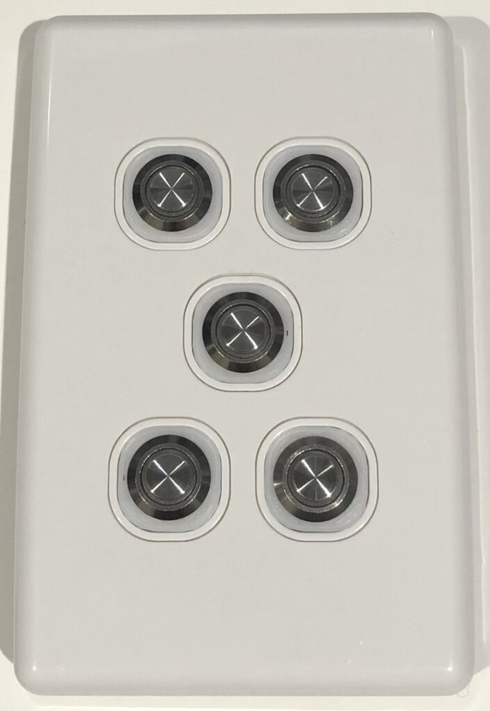
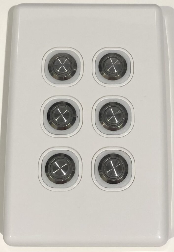
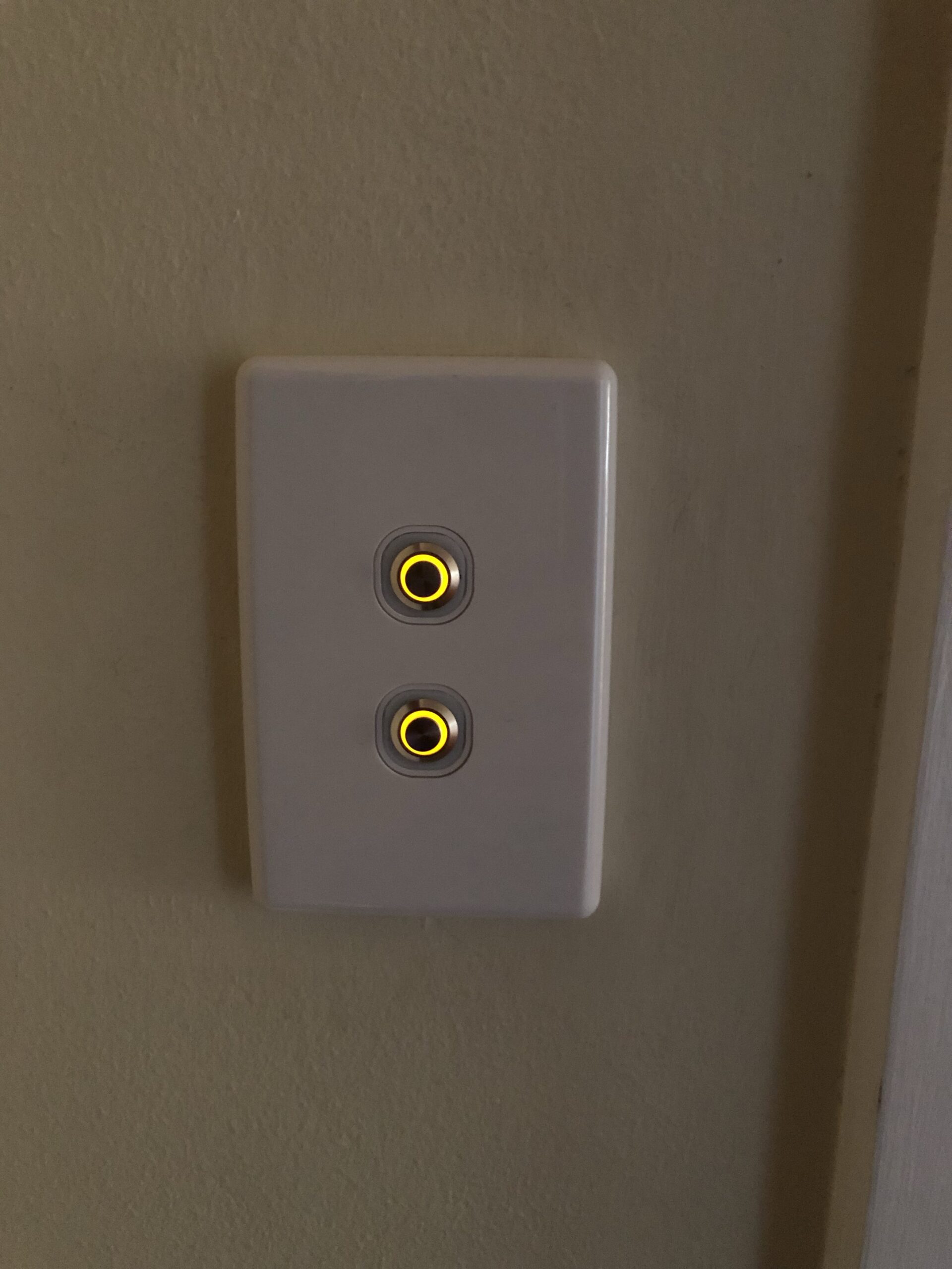
In situ
Below are the different face plates with 1 through 6 buttons. At the moment we are only using the 1, 2 and 3 button plates around the house, however the buttons are performing excellently. Using proper plates with a mechanism insert means they also feel a lot nicer and look at lot better.
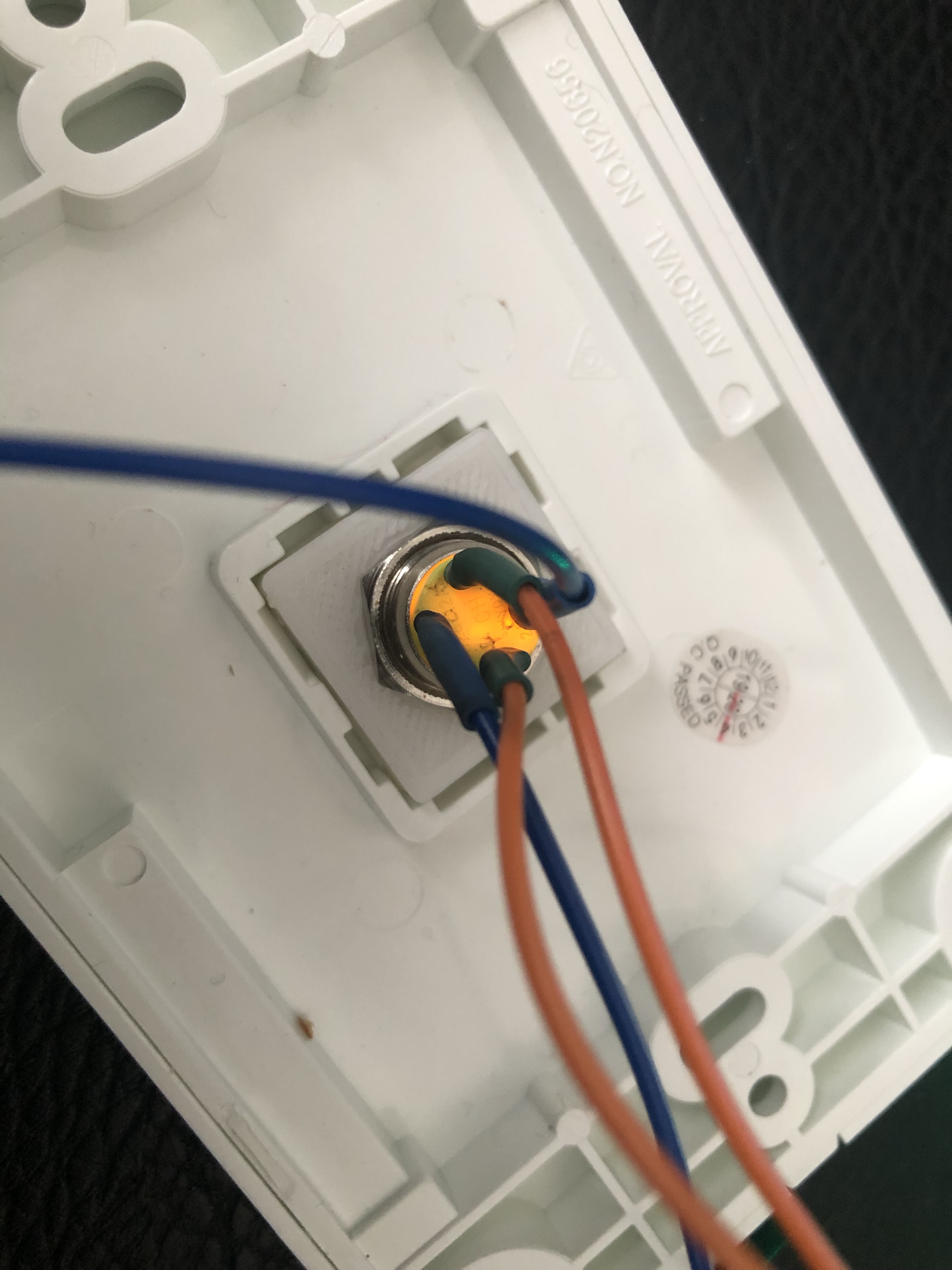
Behind the buttons
At the moment each button is soldered to some jumper wire which connects to the Ethernet run with either splice crimps or less permanent connections.
Longer term I’d like to follow a similar path to OXRS and create some PCBs that the buttons can be soldered to directly once they’re installed in the plate with a simple Ethernet jack for the wiring back to the controller.
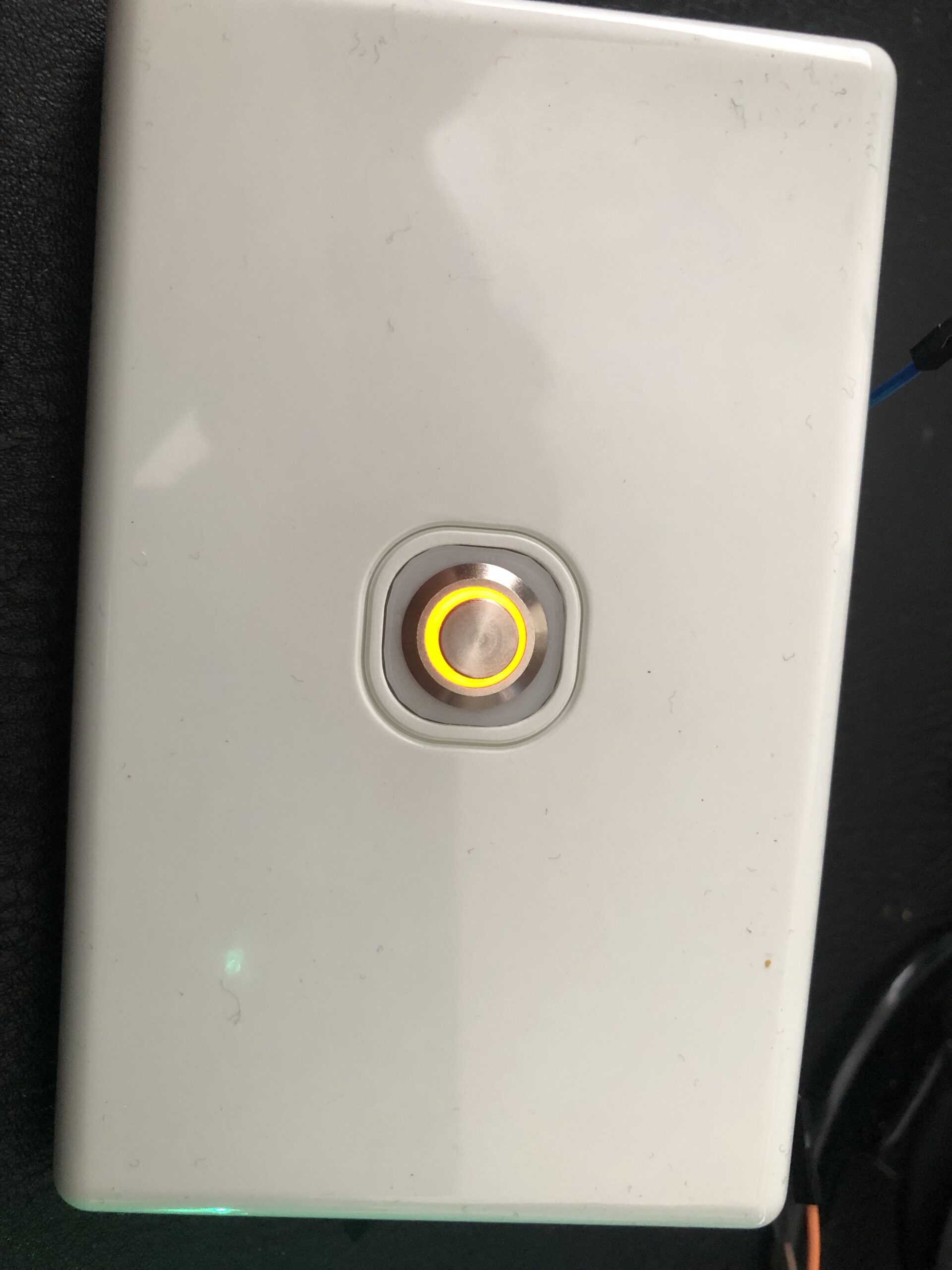
Illuminating the buttons
We use PWM to control the brightness of the LED rings instead of just having them on or off. In the future I plan to use the LED rings to indicate different things in different scenarios, however for now this means at night when the lights are off the ring can glow just enough for it to be easy to find the button and we can set the LED to reflect the state of the attached lights.
Here are some photos of the buttons illuminated:
Here is a video showing a light button in action:
There’s also a video of the two button version if that appeals.
The First Prototype Controller
In the time it has taken to write this post I’ve also ordered enough components to put together two prototype controllers – one for the house and one for the garage.
The first controller prototypes will be ESP32 based and will use:
- Screw terminals to reduce the chance of wiring faults
- PCF8575 I/O expander(s) for the button inputs
- SX1509 I/O expander(s) for the LED rings on the buttons
These prototypes should resolve our immediate concerns about the current mess of wires enveloping the six ESP8266 devices in the roof and allow us to finish installing the buttons in the remaining rooms without fearing “broken” buttons.
I’m hopeful that I can find the time to add Ethernet for more reliable communication and PoE – even if it’s just using a splitter for now.
I suspect this will tide us over before either going all-in on OXRS or going down the PCB design path for the controller.